Tone Bender MKIII Instructions
← Back to product pageBuild Difficulty: Multimeter Required
Components
| C1 | 100nF |
| C2 | 220pF |
| C3 | 22uF Electrolytic |
| C4 | 220nF |
| C5 | 10uF Electrolytic |
| C6 | 100nF Electrolytic |
| C7 | 2n2 |
| C10 | 10nF |
| C11 | 10nF |
| C12 | 100uF Electrolytic |
| R1 | 1M |
| R2 | 47K |
| R3 | 220K |
| R4 | 10K |
| R5 | 10K |
| R6 | 3K3 |
| R8 | 18K |
| R9 | 10K |
| R11 | 10K |
| R12 | 10K |
| R13 | 220K |
| D1 | 1N270 |
| D2 | 1N4001 |
| D3 | 1N4148 |
| Q1 | PNP Germanium |
| Q2 | PNP Germanium |
| Q3 | PNP Germanium |
| IC1 | 7660S |
| VOL | 100K Linear |
| FUZZ | 100K Linear |
| TONE | 100K Linear |
Build Notes
To use a PNP Tone Bender with a normal 9V power supply, this circuit includes a power inverter section which is C10, C11, C12, D2, D3 and IC1 which is generates the -9V required. Unless you have a seperate positive ground PSU and know what you're doing, you should use all these components, otherwise omit them and solder a jumper between the pins of JP1. (Do NOT connect the jumper if using the power inverter or you will get a short circuit).
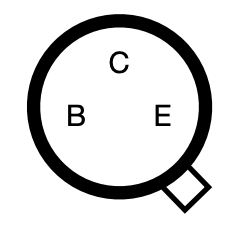
Transistors
There are many different types of Germanium PNP transistors that you could use with this circuit. You can get matched sets for Tone Benders, but the rough guide is the use one with a gain (hfe) of 45-55 for Q1 and 90-110 for Q2 and Q3. Use sockets if you want to experiment with different kinds, and mind the pinout.
Pinout:
Jumpers
Where a component is listed as jumper, solder a piece of wire between the pads to make a connection.
Board Connections
The PCB connections are labelled as the following: I - Input, O - Output, V - 9V DC in, G - Ground Potentiometers are connected from pin 1 to the square pad on the PCB.
This board was designed so you can use right-angle board mount potentiometers on it if desired, otherwise you will need to solder wired from the pads to the correct pin/lug.
Jack sleeves and DC centre pin should be connected to ground. V, LED + with a 2K2 resistor in series should be connected to the positive pin of the DC connector.

