Tone Bender MKII Instructions
← Back to product pageBuild Difficulty: Multimeter Required
Components
| C1 | 10nF |
| C2 | 4u7 Electrolytic |
| C3 | 100nF |
| C4 | 10nF |
| C5 | 4u7 Electrolytic |
| C6 | 10uF Electrolytic |
| C7 | 100uF Electrolytic |
| C8 | 10uF Electrolytic |
| R1 | 100K |
| R2 | 10K |
| R3 | 470R |
| R4 | 100K |
| ATTACK | 1K Linear |
| D1 | 1N4148 |
| D2 | 1N4001 |
| IC1 | 7660S |
| Q1 | Germanium PNP |
| Q2 | Germanium PNP |
| Q2BIAS | 100K Trimmer |
| Q3 | Germanium PNP |
| Q3BIAS | 10K Trimmer |
| VOL | 100K Log |
Build Notes
Where capacitor type isn't specified, you can use monolithic ceramic or film type.
When using PNP transistors, which the vast majority of germanium ones as used in the original pedals are, this circuit needs a -9V power supply. In order to make it work with a normal power adaptor, the PCB includes a power inverter section which uses a 7660S to generate the negative voltage rail. It is important that you use a geniune 7660S (note the S) chip, as knockoffs can make a high pitched humming sound when used in audio circuits. I recommend bitsbox.co.uk or smallbear to purchase genuine ones.
Transistors
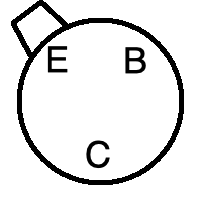
There are many different types of Germanium PNP transistors that you could use with this circuit. You can get matched sets for Tone Benders from places like smallbear, but the rough guide is the use one with a gain (hfe) of 45-55 for Q1 and 90-110 for Q2 and Q3. Use sockets if you want to experiment with different kinds, and mind the pinout. The diagram below shows the pinout on the PCB, find the datasheet for your transistors and make sure they match. It may require twisting the legs around, but the CBE layout is fairly common for germanium transistors
Biasing
To get the best sound from a Tonebender, you need to bias the transistors. This involves adjusting the trimmers and measuring the voltage between ground and the testpoints on the board (marked TP1 for Q2 and TP2 for Q3). The voltages should be between 0.75-1.5V for Q2 and between 4.5-8V for Q3. It's advised to adjust them until they sound best to you, not trying to get an exact voltage reading.
Board Connections
The PCB connections are labelled as the following: I - Input, O - Output, V - 9V DC in, G - Ground Potentiometers are connected from pin 1 to the square pad on the PCB.
This board was designed so you can use right-angle board mount potentiometers on it if desired, otherwise you will need to solder wired from the pads to the correct pin/lug.
Jack sleeves and DC centre pin should be connected to ground. V, LED + with a 2K2 resistor in series should be connected to the positive pin of the DC connector.

