Harmonic Percolator Instructions
← Back to product pageBuild Difficulty: Easy
Components
| C1 | 100pF Silver Mica |
| C2 | 47nF Film |
| C3 | 100nF Ceramic |
| C4 | 47uF Tantalum |
| C5 | 100nF Ceramic |
| C6 | 47uF Tantalum |
| C7 | 2u2 Electrolytic |
| C8 | 1n5 Ceramic/Film |
| R1 | 750K |
| R2 | 220K |
| R3 | 91K |
| R4 | 20K |
| R5 | 4K7 |
| D1-D2 | 1N34A or other Germanium |
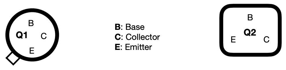
| Q1 | 2N404 |
| Q2 | 2N3565 |
| HARM | 100K Log |
| BALANCE | 50K Log |
Build Notes
C1 was originally a silver mica capacitor but these can be quite expensive, but a ceramic capacitor will work as well. Electrolytic capacitors can be used for C4 and C6. The original transistors can be hard to find as they are no longer manufactured, but a common replacement for Q2 is the popular BC108 or 2N3904. For the germanium Q1 you can try a different low gain (40-60 hfe) PNP. I suggest socketing these so you can swap them out easily if you want to test a few different ones. Check the datasheet online for your transistors for the pinouts!
The pinout on the PCB is:
Board Connections
The PCB connections are labelled as the following: I - Input, O - Output, V - 9V DC in, G - Ground Potentiometers are connected from pin 1 to the square pad on the PCB.
This board was designed so you can use right-angle board mount potentiometers on it if desired, otherwise you will need to solder wired from the pads to the correct pin/lug.
Jack sleeves and DC centre pin should be connected to ground. V, LED + with a 2K2 resistor in series should be connected to the positive pin of the DC connector.

