Blues Breaker Instructions
← Back to product pageBuild Difficulty: Medium
Components
| C1 | 10nF |
| C2 | 47pF |
| C3 | 10nF |
| C4 | 10nF |
| C6 | 100nF |
| C7 | 10nF |
| C8 | 10nF |
| C9 | 100nF |
| C10 | 100uF Electrolytic |
| C11 | 100uF Electrolytic |
| C12 | None |
| R1 | 1M |
| R2 | 4K7 |
| R3 | 3K3 |
| R4 | 1M |
| R5 | Jumper |
| R6 | 4K7 |
| R8 | 6K8 |
| R9 | 220K |
| R10 | 6K8 |
| R11 | 1K |
| R12 | 1M |
| R13 | 47K |
| R14 | 47K |
| D1 | 1N4148 |
| D2 | 1N4148 |
| D3 | 1N4148 |
| D4 | 1N4148 |
| D5 | None |
| D6 | None |
| D7 | 1N4001 |
| IC1 | TL072 |
| VOL | 100K Log |
| GAIN | 100K Linear |
| TONE | 25K Linear |
| PRESENCE | Jumper pins as shown |
Build Notes
Where capacitor type isn't specified, you can use monolithic ceramic or film type. Where a component is listed as jumper, you should solder a wire link between the pads.
Note: there is no C5 or R7
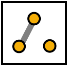
Join pins 2 and 3 of the presence pads on the PCB as shown:
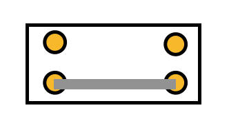
Solder a jumper wire between the bottom two pads of the diodes switch pads as shown below:
Board Connections
The PCB connections are labelled as the following: I - Input, O - Output, V - 9V DC in, G - Ground Potentiometers are connected from pin 1 to the square pad on the PCB.
This board was designed so you can use right-angle board mount potentiometers on it if desired, otherwise you will need to solder wired from the pads to the correct pin/lug.
Jack sleeves and DC centre pin should be connected to ground. V, LED + with a 2K2 resistor in series should be connected to the positive pin of the DC connector.

