Tone King Instructions
← Back to product pageBuild Difficulty: Easy
Components
| C1 | 10nF |
| C2 | 100pF |
| C3 | 10nF |
| C4 | 10nF |
| C6 | 100nF |
| C7 | 10nF |
| C8 | 10nF |
| C9 | 1uF Film/Monolithic Ceramic |
| C10 | 100uF Electrolytic |
| C11 | 100uF Electrolytic |
| C12 | 1uF Electrolytic |
| R1 | 1M |
| R2 | 27K |
| R3 | 33K |
| R4 | 1M |
| R5 | 10K |
| R6 | 10K |
| R8 | 6K8 |
| R9 | 220K |
| R10 | 6K8 |
| R11 | 1K |
| R12 | 1M |
| R13 | 47K |
| R14 | 47K |
| D1 | MA856 |
| D2 | MA856 |
| D3 | MA856 |
| D4 | MA856 |
| D5 | 1S1588 |
| D6 | 1S1588 |
| D7 | 1N4001 |
| IC1 | TL072 |
| VOL | 100K Log |
| GAIN | 100K Linear |
| TONE | 20K Linear |
| PRESENCE | 50K Linear |
| DIODES_SWITCH | 2 Way DIP Switch |
Build Notes
Where capacitor type isn't specified, you can use monolithic ceramic or film type.
Note: there is no C5 or R7
Jumpers
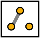
Where a component is listed as jumper, solder a piece of wire between the pads to make a connection. Where the presence trimmer is not used, you should put a jumper between pins 2 and 3 like the diagram below.
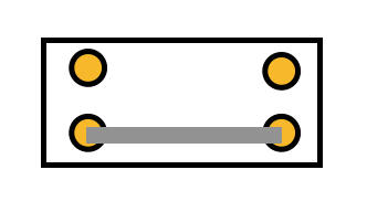
If you're building the Bluesbreaker, put a jumper between the bottom two pads of the DIP switch:
Adjust the presence trimmer to your preference, or it can be wired to an external 50K pot if you want to have it available to change. The DIP switch can be used to turn the different clipping sections on or off. See which sound you like best.
Board Connections
The PCB connections are labelled as the following: I - Input, O - Output, V - 9V DC in, G - Ground Potentiometers are connected from pin 1 to the square pad on the PCB.
This board was designed so you can use right-angle board mount potentiometers on it if desired, otherwise you will need to solder wired from the pads to the correct pin/lug.
Jack sleeves and DC centre pin should be connected to ground. V, LED + with a 2K2 resistor in series should be connected to the positive pin of the DC connector.

